

GMC Cx is always innovating and finding superior ways to verify and document construction quality. We believe in using the right tool for the right job which is why we leverage custom built Skyspark Analytics for Monitoring Based Commissioning and Facility Grid as a cloud-based commissioning platform.
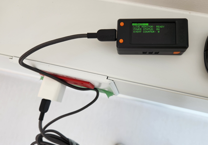
Our innovation continues with our recently developed Transfer Timer™. This portable device provides precise, real-time and recorded data on the power transfer performance (transfer time) of Emergency Power Supply System (EPSS) and Standby Power Systems (SPS).
According to the U.S. Energy Information Agency, nearly all electrical customers experience at least one electrical utility outage each year. On average, each outage lasts 60 minutes or more. Power outages can have significant impacts on commercial facilities, affecting operations, revenue, and safety. Risks include Operational Downtime, Hardware Damage, Workplace Hazards and Restoration Expenses. To protect against these risks many facilities install backup power systems including generators, ATSs and UPSs to provide facility power during a utility outage.
What Is Transfer Time?
Transfer time refers to the interval required for an EPSS or SPS to detect a failure in the primary (utility) power source and engage the backup (emergency or standby) power source, such as a generator or battery. During this interval, any load connected to the system will experience a temporary loss of power. In critical applications, even a brief disruption can have far-reaching consequences, making transfer times a key performance metric for EPSS.
Why Transfer Time Matters?
The significance of transfer time varies depending on the application:
Healthcare Facilities: Hospitals rely on uninterrupted power for life-support equipment, operating rooms, and patient monitoring systems. Regulatory standards, such as those from the National Fire Protection Association (NFPA), dictate stringent transfer time requirements for healthcare facilities.
Data Centers: Even a few milliseconds of downtime can disrupt IT operations, leading to data loss, service outages, and potential financial losses. Tier-rated data centers often have specific requirements for transfer times to meet service level agreements (SLAs).
Industrial Applications: In plants, delays in power transfer can halt operation and production, damaging equipment and leading to costly downtime.
Laboratories and other Facilities: Power disruptions cause interruptions in life safety systems such as laboratory exhaust and ventilation as well as emergency lighting.

Standards and Regulations
Various standards govern the acceptable transfer times for emergency power supply systems. Most common is NFPA 110 Chapter 4 and (NFPA 70) NEC 700.12.
Emergency systems are defined by NFPA 70, Article 700 and are intended to automatically supply illumination, power, or both, to designated areas and equipment in the event of failure of the primary power supply or in the event of accident to elements of a system essential for life safety.
NFPA 110 classifies EPSS Types. The type defines the maximum time, in seconds, that the EPSS will permit the load terminals of the transfer switch to be without acceptable electrical power.
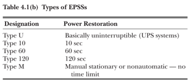
Types are distinguished by the types of loads they carry and have different equipment and installation standards. Level 1 (Type 10) EPSS systems provide power where failure would result in “loss of human life or serious injuries”. Level 2 (Type 60) EPSS systems carry loads “less critical to human life and safety”.
Both NFPA and NEC standards specify a maximum transfer time of 10 seconds for Type 10 EPSSs. Specifically, NFPA says the Type defines the maximum time, in seconds, that the EPSS will permit the load terminals of the transfer switch to be without acceptable electrical power.
Note that 10 seconds is not the generator start time as most commonly misquoted, it is the time interval between when acceptable power is lost at the ATS load terminals and when acceptable power is restored.
The load terminals are the output of the ATS. Acceptable electrical power quality refers to a steady electrical supply where the voltage remains within a specified range (typically +/- 5% of the RMS voltage), the frequency is stable near its rated value, and the waveform is a smooth sine wave with minimal distortion. Power can also be deemed as “acceptable” so long as it falls within the acceptable load pick-up parameters of the ATS and it does not cause the load’s protective functions to disconnect it from the EPSS.

Backing up on the Backup – What is an EPSS or SPS?
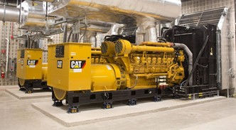
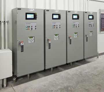
Emergency Power Supply System (EPSS) and Standby Power Systems (SPS) consist of two main components. A Generator, which is your emergency or alternate source, and a Transfer Switch, in this case an Automatic Transfer Switch (ATS).

There are many different types of Generators and ATSs. In this blog I am focusing on Diesel Generators and Open-Transition Switches (as opposed to Closed-Transition, Static Transfer or Manual Transfer Switches). NFPA 110 requires mechanical interlocking or an approved alternate method to prevent the inadvertent interconnection of the primary power supply and the EPS, or any two separate sources of power. An open transition switch uses “break before make” sequence of operation to prevent inadvertent interconnection. Closed transition switching is used in applications where the interruption of power even for a few milliseconds is not acceptable.
The Role of the Generator in your EPSS
A generator provides the source of backup power when the primary power source fails. It converts fuel electrical energy to sustain operations during outages. The generator (or Emergency Source) maintains consistent power quality and can run for extended periods, provided they have sufficient fuel.
The Role of the ATS in Your EPSS
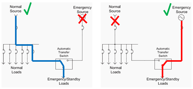
The ATS is the traffic light between the normal power, the generator, and the building’s emergency or standby electrical distribution system. When the ATS detects a power outage, it sends a start signal to the generator and automatically disconnects the emergency loads from the utility grid (normal power) and connects it to the generator. This transition ensures your essential systems stay operational with minimal downtime.
The ATS is self-acting (automatic) governed by dedicated control logic. The controller is typically microprocessor-based and constantly monitors the electrical parameters (voltage, frequency) of primary and alternate power sources. Most automatic transfer switches seek connection to the normal power source (utility) by default and will only connect to the emergency power source when required or requested to do so (operator command).
Before switching to emergency power, the ATS must perform a few critical checks and work through it’s programmed delays.
Why Does it take 10 Seconds to Transfer?
A lot of steps take place in the 10 seconds including ATS delays and generator start. ATS have built-in safety time delays for several important reasons. Duthie Power Services (https://duthiepower.com/) has a great summary about ATS delays on their website:
1. Avoiding “False Starts”
Power outages aren’t always black-and-white events. Sometimes, the grid experiences momentary glitches—think of those brief flickers when the lights dim but come back immediately. The delay gives the ATS time to confirm that the outage is real and not just a temporary blip.
2. Prevent Electrical Backfeeding
One of the main reasons there’s a time delay between when you lose utility power and when your generator starts is to prevent electrical backfeeding to the grid.
3. Protecting Sensitive Equipment
Power outages often come with voltage irregularities and surges, especially when the grid tries to stabilize before shutting down completely. This is particularly critical for facilities relying on sensitive machinery or electronics.
4. Allowing the Generator to Reach Full Speed
Generators need a few seconds to warm up and stabilize at their rated speed and output. The ATS waits for this stabilization to ensure your generator is delivering clean, steady power before connecting it to your building. This prevents issues like voltage sags or frequency mismatches that could damage your equipment.
How Long Is the ATS Transfer Delay?
Typically, the pre-programmed transfer delay is preset at 5-10 seconds for most commercial systems, but this can vary depending on the manufacturer and your specific setup. Most ATS units allow adjustment to the delay to suit your facility’s needs, within safe parameters.
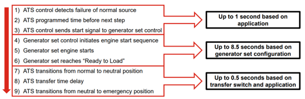
The Transfer Steps
Cummins (www.cummins.com) has a good presentation which covers the nine typical steps during a transfer. In 10 seconds all nine of these steps need to occur.
1) ATS control detects failure of normal source
2) ATS programmed time before next step
3) ATS control sends start signal to generator set control
4) Generator set control initiates engine start sequence
5) Generator set engine starts
6) Generator set reaches “Ready to Load”
7) ATS transitions from normal to neutral position
8) ATS transfer time delay
9) ATS transitions from neutral to emergency position
Do you know how long the transfer took place?
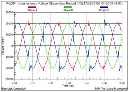
The best and most accurate way to time the transfer would be to connect a three-phase power quality analyzer with logging capabilities and millisecond resolution to the ATS load terminals.
However, there are a couple of issues with this method:
1. These power analyzers are expensive. Typically costing tens of thousands of dollars.
2. The ATS load terminals are typically live, requiring hot work to open the ATS and attach the current probes and voltage clips. Alternatively, two disruptive outages to attach and remove the probes would be required.
3. The current probes and voltage clips may not be installed correctly, resulting in bad data.
4. After the event, you will need to connect the power analyzer to a computer, download the data, trend the voltage, and examine the resulting sine waves and convert hertz to seconds. This takes time and the expertise to review the data may not be readily available to make any adjustments that day.
The most common way I have seen to time the transfer is a stopwatch. Again, there are a few issues with this method:
1. The start time is not consistent or guaranteed to be accurate
2. The stop time is not consistent or guaranteed to be accurate
3. There is no way to record multiple outages
Necessity is the Mother of Invention
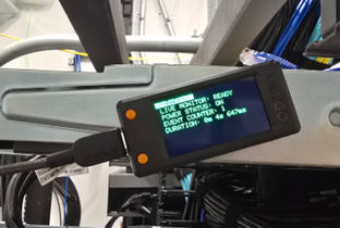
The need of a simple device to accurately take and record transfer time is where our Transfer Timer™ idea became a reality. Just like an ATS, the Transfer Timer™ is governed by dedicated control logic which constantly monitors the voltage of its power source. Once it recognizes the power has been disconnected, it starts a timer. When the power is restored, the timer stops. The timer is accurate down to 75 milliseconds. One voltage cycle at 60 Hz takes 16.67 milliseconds, so the timer can measure events after only 4 voltage cycles.
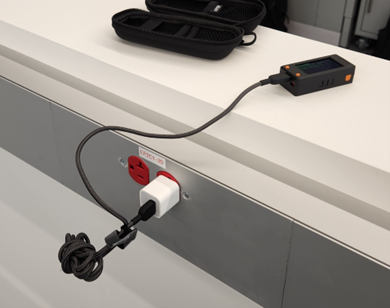
The Transfer Timer™ is powered and monitors power from any emergency 120V or 240V source. While it is not connected directly to the ATS load terminals, it can easily be connected to any receptacle connected to the EPSS or SPS. The time delay between the load terminals and a receptacle is about 50 milliseconds and, even though this is a short amount of time already, this delay is consistent between losing and regaining power, negating the effect of the delay on the final recording.
Every power outage event is stored in its internal memory and the unit can store hundreds of events. The Transfer Timer™ has an internal battery which keeps it (and the timer) running while the power is off.
The Switch Back
After utility power has been restored the ATS will transfer back (assuming it is set to "normal seeking" not "power seeking.”) This transfer will not occur instantly. The ATS has a re-transfer timer or a Time Delay Return. This timer is adjustable and is typically factory set at 12 minutes (NFPA 110 requires a minimum of 5 minutes). It is initiated upon the restoration of normal power and will inhibit the switch from retransferring to the normal source until it has timed out. If at any time during the timing cycle normal power is not maintained, this timer will be terminated and will be reinitiated when normal power returns.

There is no code or standard requirement for the switch back time. The typical transfer back time (once the time delay is complete) is around 100 milliseconds, depending on the equipment. However, loads connected to the ATS are without power again. This is a brief interruption, but if it is long enough it may exceed some electronics Hold-Up Time. Depending on the application, the length of the hold-up time varies from a half or full cycle of the incoming AC 50/60Hz voltage. This is typically 8 to 20 milliseconds at 100% load.
Once again, the Transfer Timer™ can play an important role in verifying the performance of the EPSS or SPS system. While remaining plugged in, it will record the Transfer Times both from Normal to Emergency and then from Emergency back to Normal.
The final step in the sequence is the generator cool down. When all breakers/ATSs are back to normal position the ATS starts the generator cooldown or engine stop timer. The delay engine stop timer will begin its timing cycle, and the generator runs unloaded for the duration of this cycle. When the timer completes its timing cycle, the generator will stop. Per NFPA 110, a minimum time delay of 5 minutes is provided for the unloaded running of the generator prior to shutdown to allow for engine cool down.
EPSS Installation Acceptance Testing and Operational Testing Frequency
Legally required standby system testing consists of acceptance testing and operational testing. These installation acceptance tests are applied to the new components of an EPSS, whether installed for a new or existing system. An on-site acceptance test shall be conducted as a final approval test for all EPSSs. All new EPSS equipment is acceptance tested before a Certificate of Occupancy is issued and verified by the local AHJ and Fire Marshall. After initial commissioning, per NFPA 110 section 8.4.9, Level 1 EPSS shall be tested every 36 months.
All ATSs shall be operated and exercised monthly under load per NFPA 110 section 8.4.6 and although it is not required to verify the type rating of the system during the monthly exercise test, it is required to observe and record the time delay on start. NFPA also requires an annual confirmation that the system responds within the time dictated by its rating.
Additionally, the Joint Commission who sets quality standards for healthcare also sets a Standard (EC.02.05.07 EP7) requires that all ATSs are tested monthly with documentation of the result.
The GMC Cx Transfer Timer™ represents a significant advancement in the measurement and verification of power transfer performance for Emergency Power Supply Systems (EPSS) and Standby Power Systems (SPS). By providing precise, real-time data on transfer times, this innovative device addresses the critical need for reliable backup power in various applications, including healthcare, data centers, industrial facilities, and laboratories. The Transfer Timer™ not only enhances the accuracy of transfer time measurements but also simplifies the process, making it more accessible and efficient for facilities to ensure compliance with stringent standards and regulations. As power outages continue to pose risks to operations and safety, the Transfer Timer™ stands out as a valuable tool in maintaining uninterrupted power and safeguarding essential systems.
References:
Comments